The implant
Recently I was implanted with a wireless capsule to monitor stomach pH (specifically, the Medtronic “Bravo Reflux Capsule”). It’s a sensor that’s temporarily attached to your lower esophagus, in order to measure the pH in-situ. This is a pretty common procedure ever since it supplanted the previous gold standard of cathether-based ambulatory pH monitoring, with a cathether running through your nose.
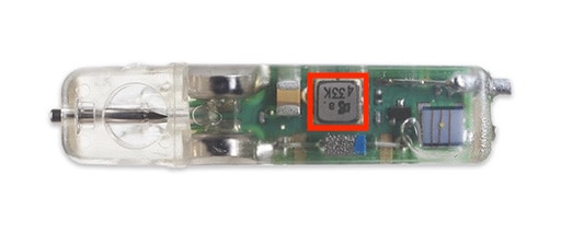
Bravo pH capsule transmitter, about the diameter of a pencil
original image from Medtronic. A very coincidental inductor marking of “433” made me want to look more into the operations of the transmitter more.
Aside: Unfortunately you do lose intraluminal impedance measurements with this type of small wireless sensor, but that’s a separate story.
Because the capsule transmitted wirelessly, it gave me an opportunity to see if I can capture the data myself, given that when I examined the patient demo capsule, it seemed to be a very small, very low-power transmitter with 2 watch-battery-sized coin cells as a power source. This likely meant that this device is:
- very simple in signaling
- very short range
- possibly unencrypted (?) depending on year of design
But how did it communicate wirelessly? The medical tech described the communication as “Bluetooth-like”, which would likely be a no-go for data capture depending on the version of Bluetooth. Plus, there are a plethora of specialized low power transceiver chipsets these days in the license-free ISM bands (which you may know as Wi-Fi and Bluetooth), due to the thriving mobile and IoT markets. But the first thing that caught my eye was the manufacturer’s image: “433”. Note that this was just a coincidental inductor marking, but it ended up being the prompt for me to look deeper at the FCC filing.
433 MHz
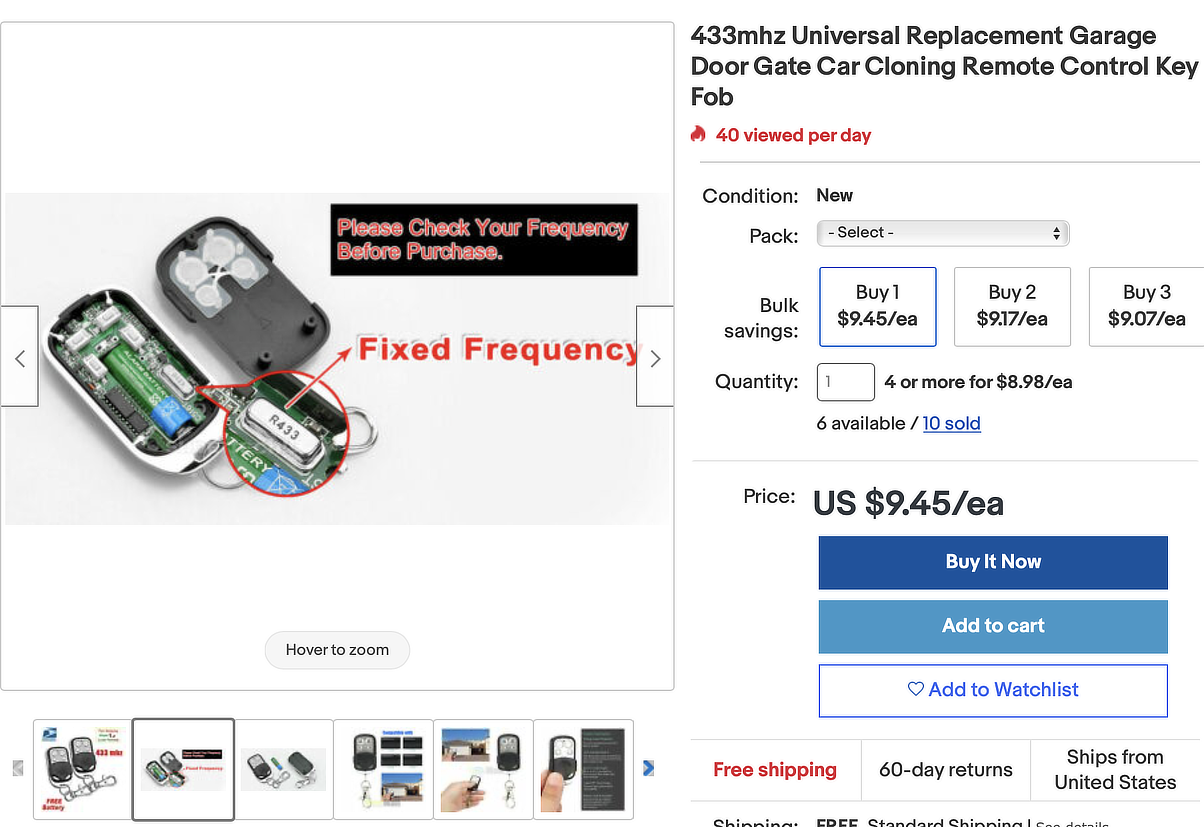
Generic 433 MHz garage door fob
original image from eBay
433 MHz is a pretty popular part of the radio spectrum for consumer electronics. Licensed “Part 15” devices in the US, including many garage door openers, remote wireless sensors & switches, camera flash triggers, and even popular motion-detector security systems of all sorts can use this frequency, especially if they use inexpensive radio designs, often designed and matured before the IoT boom.
They’re limited to very low power here in the US (in Europe, this band is license-free ISM), which is perfectly fine for the type of short-range applications you might expect from, say, your car or garage fob.
Aside: The ubiquity of 433 MHz low-powered radio has caused some… denial-of-service security vulnerabilities in aforementioned popular security systems.
I wanted to be able to see if I can decode the data from this implant in the few short hours I have while tired from the procedure. I figured that a great resource for this, especially with medical devices, is the manufacturer’s FCC filings. So let’s look up the FCC filings for this medical device and see 1) if it is in fact 433 MHz, and 2) if it’s easy to decode!
FCC filing diving
FCC filings often contain a treasure trove of information. We’re looking for a few specific items like the transmission frequency, the data encoding, and any transmission examples would really get us our information faster without extensive manual reverse engineering.
A search with the terms “fcc bravo pH” nets us the following from the excellent FCC ID aggregator site.
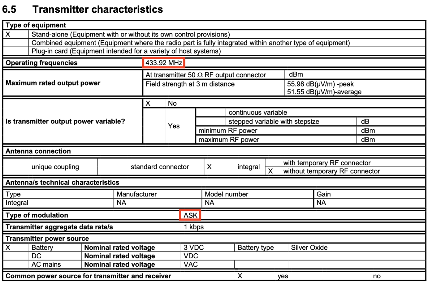
433.92 MHz!
We can easily confirm that the device transmits on 433 MHz, and using amplitude-shift keying. Now, can we find more about its encoding protocol?
OOK-PWM encoding
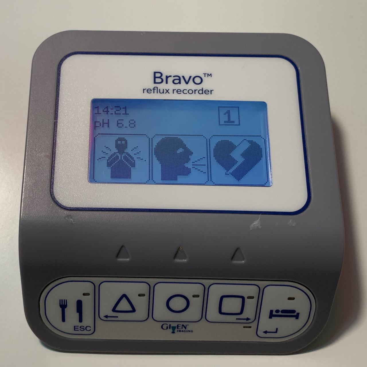
Wireless stomach pH receiver
It’s a 433 MHz OOK receiver and datalogger
As we suspected, the device is a Part 15 433 MHz device; we can see that the Bravo capsule was originally made in 2001 by Given Imaging, now Medtronic from the Covidien merger.
We can also see that the max “field strength at 3m distance”, a standard measurement of transmitter power, is roughly 56 dBμV/m. Converting that to emitted power:
we get 0.12 μW at the transmitter, or -39 dBm (or as WolframAlpha helpfully illustrates, 4 joules/year). That is very low power!
Aside: we can use an RF link budget calculator to calculate that, with a highly inefficient chip antenna on the unit with roughly -10 dB of losses, we easily approach -99 dBm of receive signal at a distance of ~10-15 meters. Add the fact that your own body is attenuating the signal, no one is going to really pick up this signal easily outside of a dozen meters. This is a great characteristic for the privacy of a medical device.
Can we find more information about its encoding protocol from these documentation? The original RF test report has a lot more information:
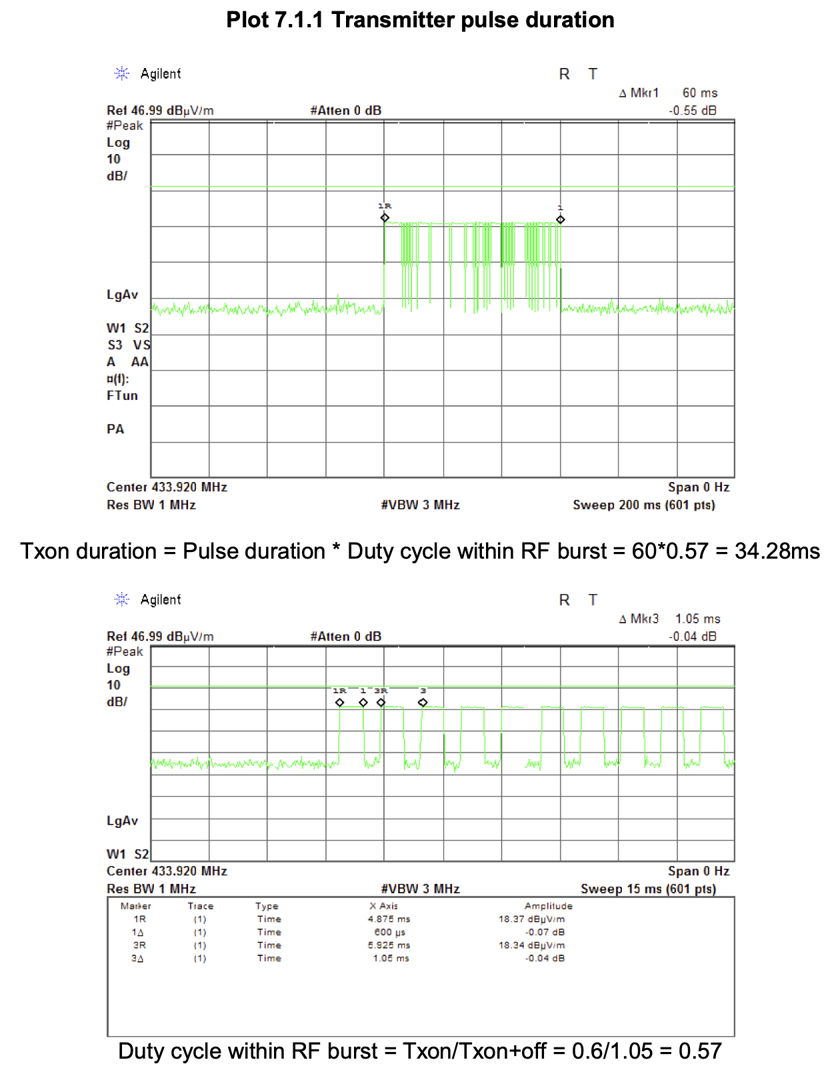
ASK/OOK encoding
The data appear to be encoded using On-Off Keying, with a couple of different pulse widths encoding binary information.
From this, we understand that we’re looking at a transmitter that encodes information in a very simple way: a constant 433.92 MHz radio tone (the “carrier”) is transmitted, and that tone is turned entirely on and off to encode information (“on-off keying”, which is the simplest form of amplitude-shift keying). This is not unlike classic Morse code. Also somewhat similar to morse code, the width of how long this constant tone stays on is used to encode binary 0’s and 1’s (pulse width modulation).
So we need to pick up and decode a 433.92 MHz, OOK-PWM encoded signal. That’s how the implant is encoding and modulating its data. What about the format of the data?
59 bits of data
Lucky for us, the FCC test report has information on the data format too!
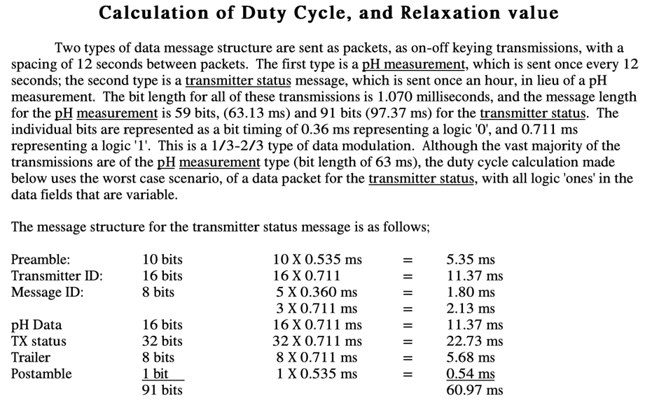
59-bit data encoding format
59 bits pH measurement, 91 bits with transmitter status, ⅓ - ⅔ PWM modulation
This invaluable information, which was meticulously documented just to estimate the theoretical highest-power transmitter power characteristics, now should make our decoding task much easier. What we should expect to have, every 12 seconds or so, is a transmitted message, with these key bit slices:
[10:26] txid
[26:34] msgid
[34:50] pH
In the description, the format between a pH-only message (every 12 seconds) and a pH message with “transmitter status” (ever hour) is $$91 - 59 = 32$$ bits. Because the only thing matching 32 bits is the “TX status” I take this to mean that those are the 32 bits that are missing from the routine pH-only messages.
So in summary:
- Modulation:
OOK_PWM - Short:
360 μs - Long:
711 μs - Max gap between bits:
1070 μs - Max between messages:
12 s - Bits:
59
With this knowledge, let’s go capture the data!
Materials
RTL-SDR
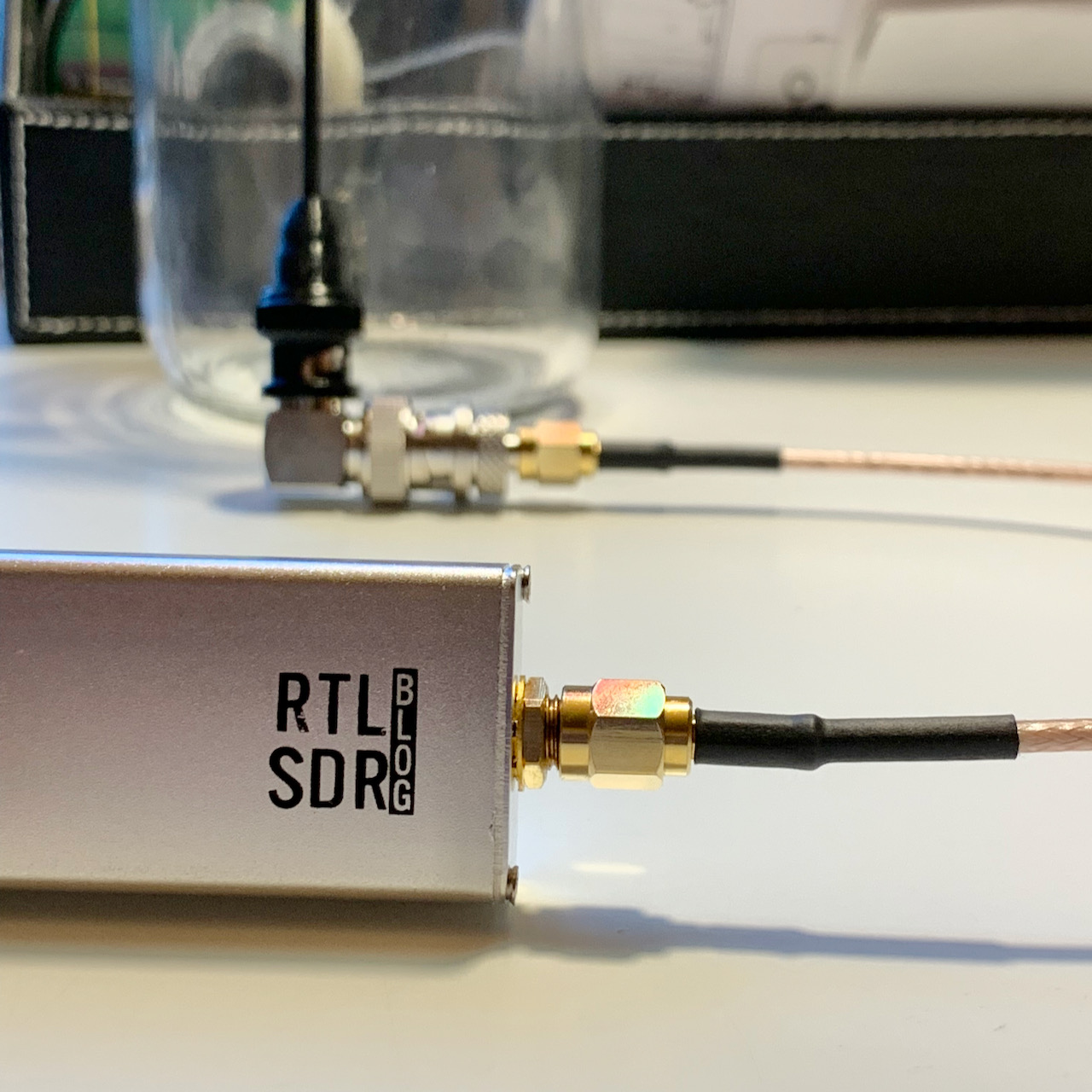
RTL-SDR with a VHF/UHF whip antenna
RF always needs a lot of adapters… antenna from here, though even a well-cut length of wire probably works fine at these very short ranges
I happen to have an RTL-SDR dongle on hand. This is of course no suprise to anyone in the radio community; the RTL-SDR is a software-defined radio based on modifying a cheap consumer European USB TV receiver chipset (the rtl2832), and therefore has a very acceptable performance receiving a wide range of radio spectrum accessible for the low price of ~$30 USD. As a result, this dongle has become a massively popular radio receiver in the tinkerer, security, and ham radio community.
Also as a result of the community, importantly, there is good software support ranging from ready-to-go Linux drivers and APIs, gnuradio compatibility, as well as easy-to-use GUI support (in the popular SDR#) under Windows.
SDR#
Under the principle of always look at your raw data, first we need to locate the signal to make sure we can at least visually confirm its existence and quality.
I fire up SDR# and tune to 433 MHz, and immediately find what I’m looking for: an OOK-modulated signal, emitted approximately every 12 seconds:
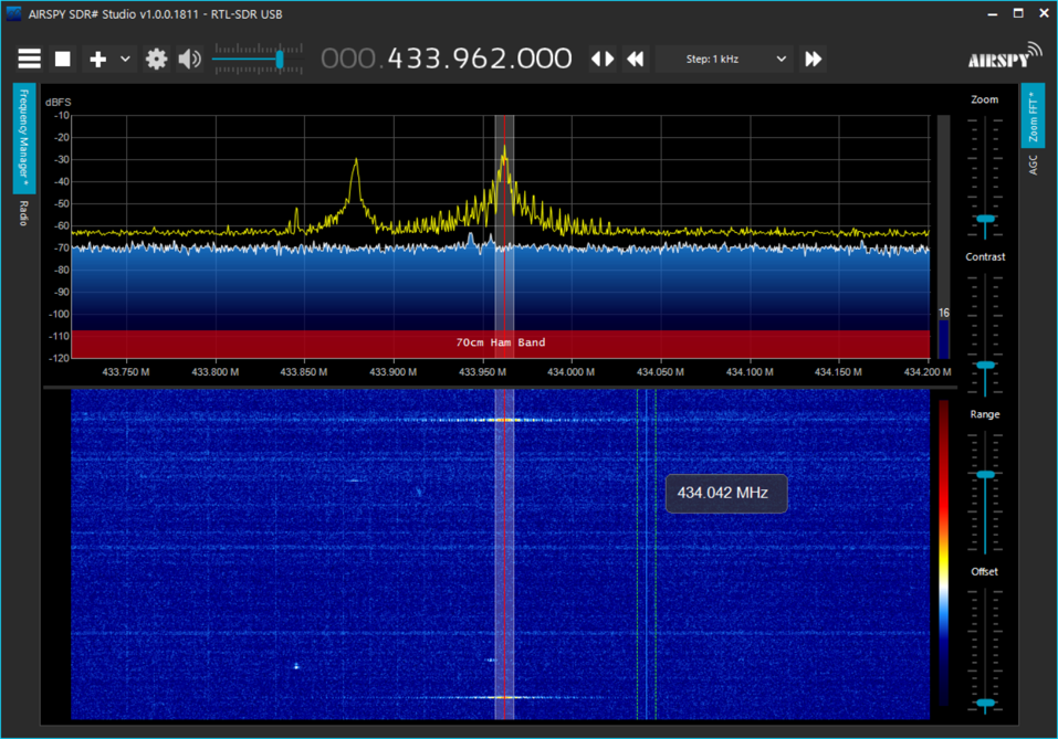
signal found!
We find a shakey low-powered signal at 433.962 MHz. Importantly, it is recurring signal, every 12-14 seconds!
You can see that the signal recurs using the bottom, colorful “waterfall” plot, where the horizontal axis is frequency, vertical axis is time (oldest bottom), and color represents the intensity of the received signal. The 2 yellow horizontal stripes represent the 2 identical signals received.
Using the top half plot’s yellow trace, which represents the highest relative signal strengths received at any particular frequency, we can also see that the peak of the 433.962 MHz signal is roughly 30-40 dB above the noise floor, which is a decent signal quality to start decoding.
RTL_433
Installing the rtl-sdr library and rtl_433 software on the nearest home Linux Ubuntu/Debian machine:
$ sudo apt install rtl-433 --no-install-recommends
Plugging in the rtl-sdr in gives this dmesg, showing it is ready to go:
[   96.451360] r820t 10-001a: creating new instance
[   96.458325] r820t 10-001a: Rafael Micro r820t successfully identified
[   96.462740] rtl2832_sdr rtl2832_sdr.1.auto: Registered as swradio0
[   96.462744] rtl2832_sdr rtl2832_sdr.1.auto: Realtek RTL2832 SDR attached
[   96.462746] rtl2832_sdr rtl2832_sdr.1.auto: SDR API is still slightly experimental and functionality changes may follow
[   96.474713] Registered IR keymap rc-empty
[   96.474798] rc rc0: Realtek RTL2832U reference design as /devices/pci0000:00/0000:00:14.0/usb1/1-4/rc/rc0
[   96.474981] rc rc0: lirc_dev: driver dvb_usb_rtl28xxu registered at minor = 0, raw IR receiver, no transmitter
[   96.475068] input: Realtek RTL2832U reference design as /devices/pci0000:00/0000:00:14.0/usb1/1-4/rc/rc0/input18
[   96.475456] usb 1-4: dvb_usb_v2: schedule remote query interval to 200 msecs
[   96.483686] usb 1-4: dvb_usb_v2: 'Realtek RTL2832U reference design' successfully initialized and connected
Receiving
Let’s start receiving using RTL_433!
First we need to add a new ad-hoc decoding protocol with our specific modulation type. Thanks to the detailed protocol description from the FCC test report, we know that that:
- Modulation:
OOK_PWM - Short:
360 μs - Long:
711 μs - Max gap between bits:
1070 μs - Max between messages:
12 s - Bits:
59
We start with the parameters we obtained from the FCC test report:
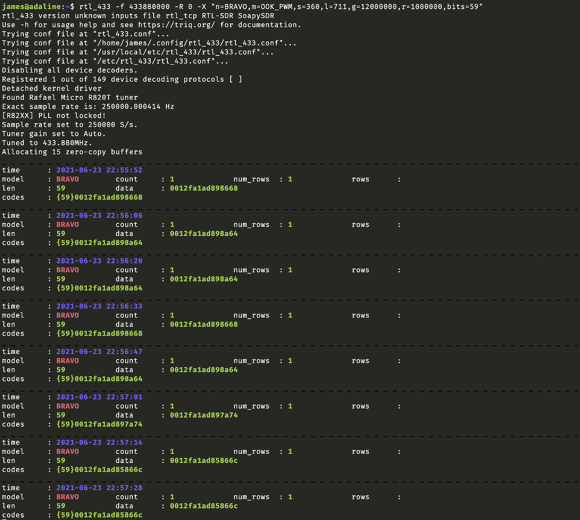
59 bit messages received!
Every ~13 seconds, we are receiving 59 bits. OOK-PWM decoding success! Note also that I accidentally mistune 80 kHz away to 433.88MHz. This didn’t matter, as the RTL-SDR was capturing at 250kHz and the signal of interest was just in the captured bandwidth.
Ok. So far, so good. We are receiving signals, of the desired bit length, of the desired modulation.
Decoding
Next, we parse the 59 bits of data in the locations of interest that we saw from the FCC filings:
[10:26] txid
[26:34] msgid
[34:50] pH
This gave me the following:
_ _ _ _ _ _ _ _ _ _ _ _ _ _ _ _ _ _ _ _ _ _ _ _ _ _ _ _ _ _ _ _ _ _ _ _ _ _ _ _ _ _ _ _ _ _ _ _ _ _ _ _ _ _ _ _ _ _ _ _ _ _ _ _ _ _ _ _ _ _ _ _ _ _ _ _ _ _ _ _ _ _ _ _ _ _ _ _ _ _ _ _ _ _ _ _ _ _ _ _ _ _ _ _ _ _ _ _ _ _ _ _ _ _ _ _ _ _ _ _ _ _ _ _ _ _ _ _ _ _
time      : 2021-06-24 00:00:55
model     : name = Given Imaging Bravo             count     : 1             num_rows  : 1             rows      :
len       : 59           data      : ffed05e526e6daa                         id        : 46103
mid       : 148          pH        : 39835
codes     : {59}ffed05e526e6daa
_ _ _ _ _ _ _ _ _ _ _ _ _ _ _ _ _ _ _ _ _ _ _ _ _ _ _ _ _ _ _ _ _ _ _ _ _ _ _ _ _ _ _ _ _ _ _ _ _ _ _ _ _ _ _ _ _ _ _ _ _ _ _ _ _ _ _ _ _ _ _ _ _ _ _ _ _ _ _ _ _ _ _ _ _ _ _ _ _ _ _ _ _ _ _ _ _ _ _ _ _ _ _ _ _ _ _ _ _ _ _ _ _ _ _ _ _ _ _ _ _ _ _ _ _ _ _ _ _ _
time      : 2021-06-24 00:01:08
model     : name = Given Imaging Bravo             count     : 1             num_rows  : 1             rows      :
len       : 59           data      : ffed05e527271a2                         id        : 46103
mid       : 148          pH        : 40092
codes     : {59}ffed05e527271a2
This is nice, but pH field still is a large 16-bit integer that is rather opaque to me. It is very unlikely the pH sensor has 16-bit precision, which would result in a pH resolution of $$\frac{14}{2^{16}} = 0.0002$$ even if it captured the full 0-14 pH range! There is no way this represented the sensitivity of the pH sensor, and there is no reason to waste precious bits sending out a 16-bit integer. What we actually expect is data in the much more common 8-10 bit range.
“Hacks all the way down”
At this point, I looked around and end up finding this amazing blog post titled “Hacks all the way down” by Justin Dolske, who also did the same receive & decode attempt, but back in 2014. This was before the time of a more dedicated tool like rtl_433, and the author had to record a slice of the baseband as audio and decode the recordings using web audio APIs.
What Dolske noted was that he was able to get ahold of was a copy of the manual (since lost to link rot), which detailed that the pH data in each transmission was actually 2 separate 8-bit measurements taken at 6-second intervals and then transmitted together every 12 seconds. This made a lot of sense! This means that the 16-bit pH field should actually be separated into 8-bit pH1 and pH2 fields.
Armed with this piece of information, we can now define the decoder protocol for rtl_433. Feel free to use this in a .conf file for your own use (e.g. rtl_433 -R 0 -c ${filename}.conf), if you ever (unfortunately) get the opportunity.
decoder {
  name = Given Imaging Bravo,
  modulation = OOK_PWM,
  short = 360,
  long = 711,
  gap = 1070,
  reset = 12000000,
  bits = 59,
  invert,
  get = @10:{16}:txid,
  get = @26:{8}:msgid,
  get = @34:{8}:pH1,
  get = @42:{8}:pH2,
  get = @50:{8}:crc
}
And we successfully obtain the pH1 and pH2 values from this protocol!
![Every ~13 seconds, we are receiving 59 bits; decoding bits [34:42] gets us pH1 and [42:50] gets us pH2, two pH values that were measured ~6 sec apart prior to transmission.](/img/capsule-decode-ph.png)
pH successfully decoded!
Every ~13 seconds, we are receiving 59 bits; decoding bits [34:42] gets us pH1 and [42:50] gets us pH2, two pH values that were measured ~6 sec apart prior to transmission.
Real pH values
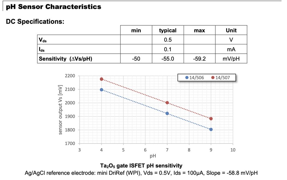
example pH ISFET sensor voltage-pH curve
We can see that this sensor has been made for the voltage-pH relationship to be roughly linear; we can work off of such an assumption for relating back the pH value with a simple linear fit. From Microsens
While I now have 8-bit pH ADC measurements (0-255), I still haven’t converted them back to real pH values. This is where I tread into speculative territory.
My training is in the area of electrophysiology, and I don’t really know much about the mechanism of action of highly integrated pH sensors such as the one this capsule uses. My shortcut approach here is to try to read the datasheet of a “typical sensor” of this type.
A search for “solid state pH sensors” revealed that these are likely going to use ISFET, or ion-sensitive field effect transistors in their design.
Looking at the spec sheet of an example pH 4-9 ISFET sensor, the MSFET 3330, we find that a standard sensor of this type likely has a linear relationship between voltage and pH, and it is likely that the medical-grade sensor is also transmitting an ADC-captured version of the voltage.
I’m not going to post my data for privacy, but for my particular unit, I then capture a few example values by hand throughout the day, based on the human-readable pH value displayed on the little screen of the wireless tranceiver unit I was carrying around:
| “pH1” | “pH2” | display pH |
|---|---|---|
| 157 | 158 | 6.1 |
| 222 | 161 | 6.4 |
| 161 | 159 | 6.2 |
| 162 | 162 | 6.4 |
| 168 | 171 | 6.7 |
| 165 | 165 | 6.5 |
| 138 | 139 | 5.4 |
| 177 | 177 | 7.0 |
Plotting pH2 ADC value specifically against the human-readable displayed pH, we arrive at the following linear fit:
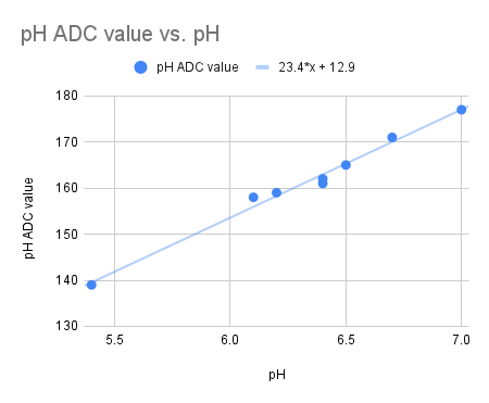
pH1 and pH2 ADC value
We get a roughly linear fit plotting between pH2 and the “displayed” pH on the patient wireless receiver unit.
This makes sense in that pH2 is likely the most recent pH value, and it makes the most sense for the receiver to display that value rather than the historical value. The other option, that the display pH is the average of pH1 and pH2, did not give a good fit.
This suggests that at least for my unit, it may be possible to roughly obtain the “real pH” from the transmitted ADC value with $$\text{pH} = \frac{\text{ADC} - 12.9}{23.4}$$
The real calibration curve is unknown. Please do not use this for medical purposes.